Packaging Details
- Unit Type:piece
- Package Weight:0.015kg (0.03lb.)
- Package Size:10cm x 10cm x 10cm (3.94in x 3.94in x 3.94in)

The wire:A set of 4pcs branching cables
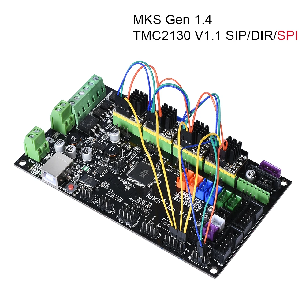
DIY TMC2130: TMC2130 V1.1 Driver
Welding Complete SPI: 4pcs SPI TMC2130 V1.1 Driver+ cables


Introduction
TMC2130-V1.1 is a new module that is optimized and upgraded to solve the problem that older drivers cannot choose to use the SPI working mode.SPI working mode of TMC2130-v1.1 can directly select driver current, driver subdivision and other parameters through firmware, which makes these parameters more accurate.Using sequexternal sequencers, it can greatly reduce the workload of the chip and effectively avoid problems such as running deviation, losting step and fault caused by the overload of the chip.
This module is similar to TMC2100, which will generate a lot of heat energy when it working. Therefore, heat sink and heat dissipation fan must be added to cool it down during the use, which reduce the occurrence of losting steps and running deviation)
Working Mode: SPI /DIR /STP
1.STP/ DIR Working Mode Wiring instructions

(1)Welding resistance at R5 position to make the driver STP/DIR working mode;
(2)Work mode selection: SDI (CFG1), SCK (CFG2)

2.SPI working mode wiring instructions:
Before wiring, you need to select the working mode of the driver module for hardware operation:
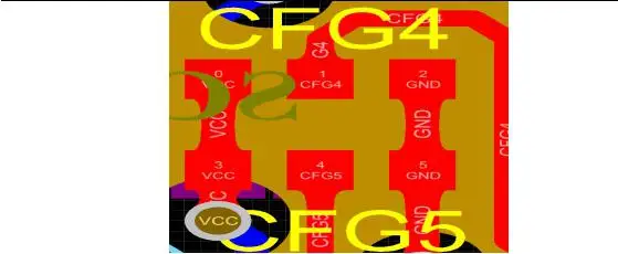
(1) Weld CFG4 and CFG5 as shown in the red area (i.e., CFG4 to GND, CFG5 to VCC); (spreadcycle mode can only be used with proper welding)
(2) Remove the resistance at the R5 position so that the driver is in SPI working mode.

wiring diagram


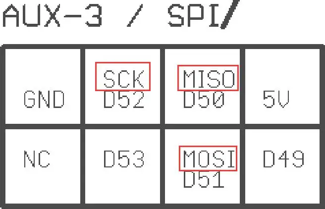
Find the AUX-3 expansion port on the board and connect to the corresponding pin:
NOTE:
1. When choosing SPI working mode, please use soldering iron carefully to prevent scalding hands. When you have finished processing, you should carefully observe whether there is residual tin residue in the module. You must clean it up to prevent it from causing the module to short circuit and burn down.
2.When you connect, please pay attention to the line sequence and IO port. The wrong connection will directly cause the driver to fail to work. Please connect carefully to the above drawing.
3.When you insert the driver into the motherboard, you should be careful to see the driver direction clearly. And must not insert the driver backwards to prevent the drive from burning.
4.The driver must do a good job of heat dissipation before working (heat sink + cooling fan) to prevent the driver from working abnormally.
5. If you have any problem, you can contact us.

Welding Complete SPI mode:


DIY TMC2130:


The Wire:


FAQ (Frequently Asked Questions and Answers)
Q:When changing firmware, TMC2130 could not be found in configuration_adv.h
A:Because of your Arduino software lacks the TMC2130 Stepper-master library file. Simply download the library file and unzip it to your library.
Website:
https://codeload.github.com/teemuatlut/TMC2130Stepper/zip/master
Q:How to add the TMC2130 Stepper-master library file
A:Download the TMC2130 steperer-master library file, unzip it, and then
Find your Arduino library, copy and paste it into your library. If your Arduino is installed on disk D, the folder path of the library is:
D:\\Program Files
(x86)\\Arduino\\hardware\\arduino\\avr\\libraries\\TMC2130Stepper-master
If it installed on disk C, the folder path of the library is:
C:\\Program Files (x86)\\Arduino\\hardware\\arduino\\avr\\libraries\\TMC2130Stepper-mas
Ter
Q: If the driver chooses SPI mode, but you want to work in STP/DIP as well, how can you do?
A: Disconnect the CFG4 and CFG5, and then connect the two pads of R5. The red part in the figure below needs to be soldered, and the red border is not connected.
Q: How to deal with the phenomenon of running deviation, fault and step loss in the printing process ?
A: Check whether the drive heat sink is loose, check whether the cooling fan can blow into the drive, and do a good job of cooling the drive, it is the best choice for you to print good products. Slowing down your printing speed can also double your printing effect.


 배송기간
배송기간