|
Packaging Details - Unit Type:piece
- Package Weight:0.048kg (0.11lb.)
- Package Size:15cm x 12cm x 10cm (5.91in x 4.72in x 3.94in)
Packaging Details - Unit Type:piece
- Package Weight:0.048kg (0.11lb.)
- Package Size:15cm x 12cm x 10cm (5.91in x 4.72in x 3.94in)
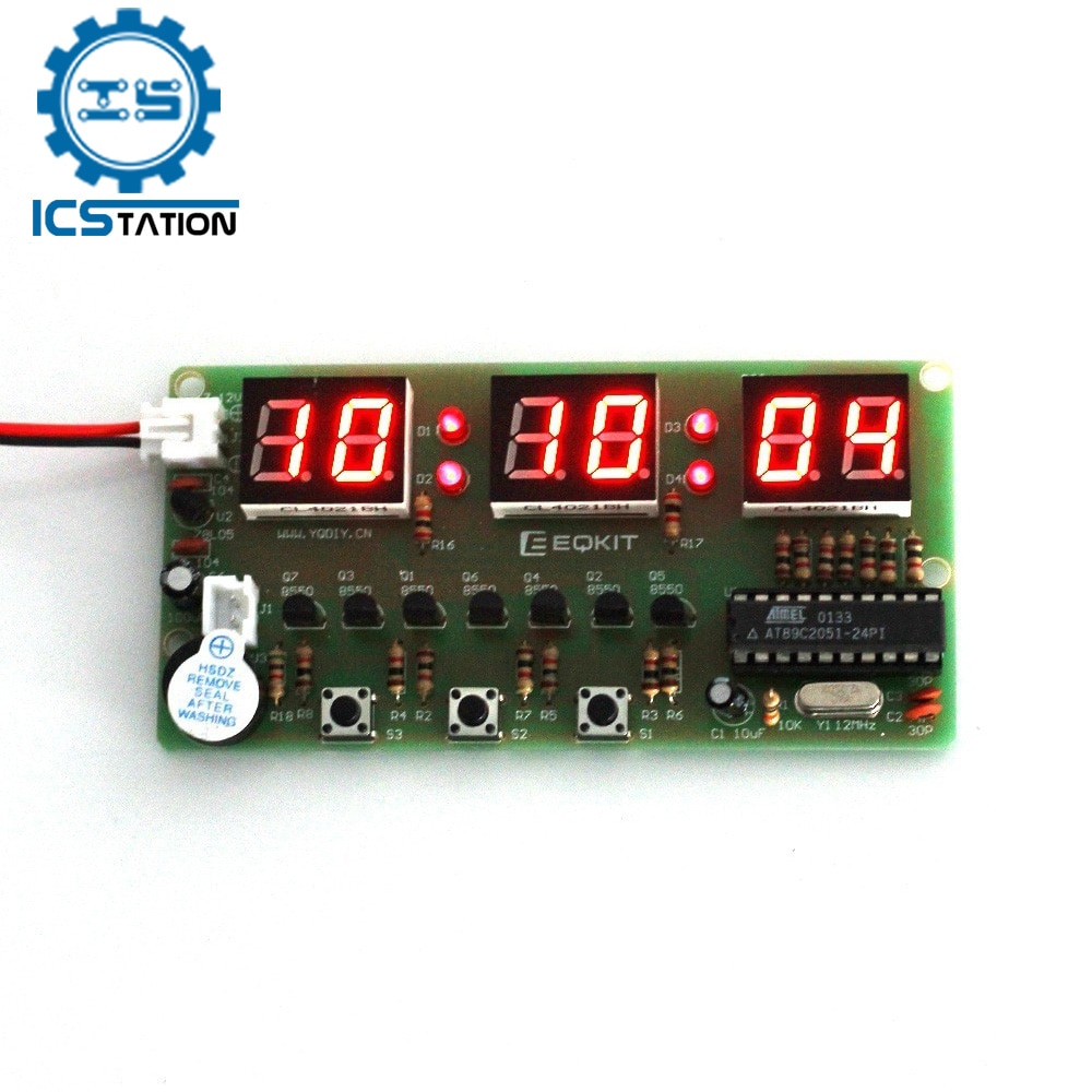
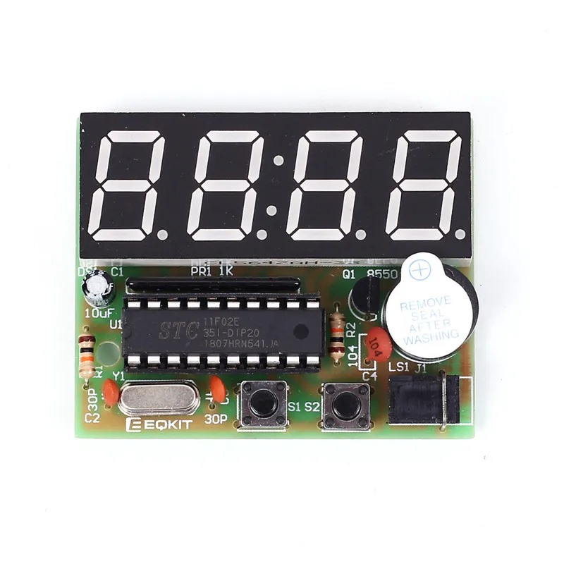
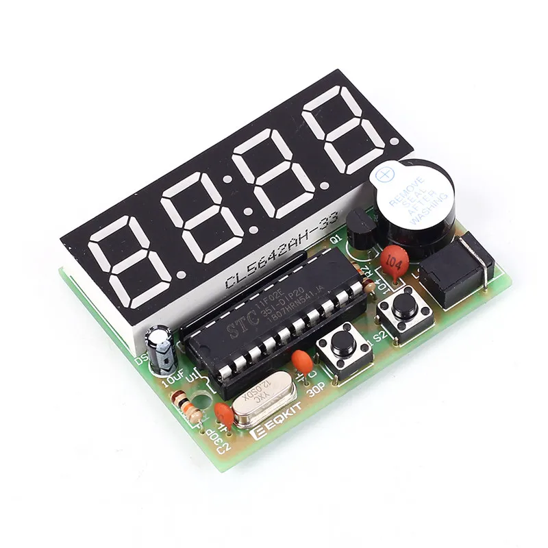
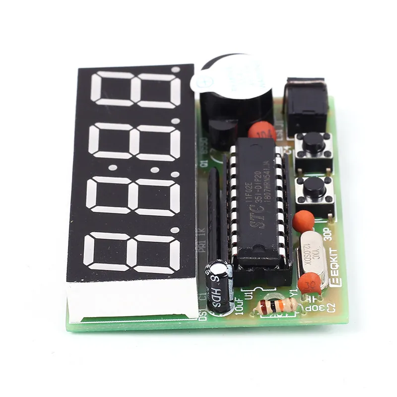
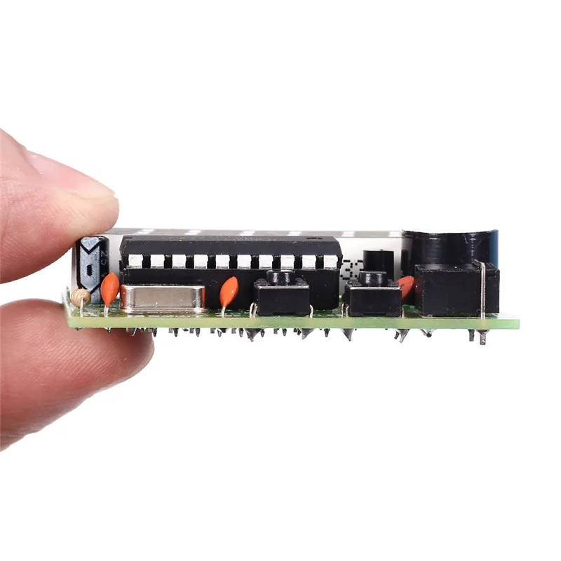
tyle="clear:both">  AT89C2051-based of four electronic clock kit Kit Model: YSZ-4
Supply voltage: 3V-6V
PCB Size: 52mm * wide 42mm
Function:
1. Seconds correction (for precise School)
2. Switch to every minute independent display interface
3. whole point of time (8-20 o\`clock chime can be turned off)
4. Two alarm settings (you can turn off the alarm function)
Kit Features:
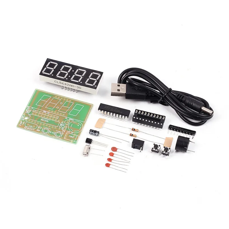
A. 0.56 inch special red digital clock for display;
B. Import AT89C2051 for master chip;
C.1.2mm thick PCB made from military grade FR-4 board;
D. accurate travel time, travel time error range error -1 to +1 seconds every 24 hours.
This kit contains a USB to 3.5mm power cord, plug in the USB charger can be used. 1. Introduction YSZ-4 four electronic clock, it takes AT89C2051 as its core, a total of 16 electronic components to come true the two channels of the alarm clock, (8:00-20:00) on time alarm ,accurate adjustment , and other functions. 2. Parameter | NO. | Parameter | Value | | 1 | Operating voltage | DC 3V-6V | | 2 | PCB board material | RF-4 | | 3 | Size | 52mm*42mm | 3. Principle The whole system by MCU minimum system, key input circuit, display circuit, buzzer circuit and power supply parts. 1>. MCU minimum system: including the U1 (AT89C2051), C1, R1 for power on reset circuit .Clock circuit is composed of C2, C3 and Y1. 2>. The pressed key input circuit:composed of S1, S2, short press the button once a loud buzzer rang, long press the button once two loud buzzer rang. 3>. The display circuit:4bits common cathode and on PR1 Resisters Packs . 4>. Buzzer circuit:composed of Q1, R2 and LS1, short press the button once a loud buzzer rang, long press the button once two loud buzzer rang. 5>. J1 is 5v power supply input terminal, C4 filtering. 4. Operation instruction It will display 12:59 when Power-on,while is normal interface("hours:minutes"). The both channels of alarm clock are opened.At the same time,the first alarm clock has been set at 13:01.the second alarm clock has been set at 13:02. After power on ,short press S2.The display of digital tube will switch between "hours:minutes" and "minutes:seconds";Long press S1 to enter the system Settings menu. there are A, B, C, D, E, F, G, H, I submenu. Short press S1 sub-menu plus increase by degrees。finally back to the normal interface A Sub menu : Correction for hours Display data will add 1 after press S2.after adjusted the A Submenu,then short press S2 to save the adjusted results and quit A submenu,enter B sbumenu B Sub menu : Correction for minutes Display data will add 1 after press S2.after adjusted the B Submenu,then short press S2 to save the adjusted results and quit B submenu,enter C sbumenu C Sub menu:on time alarm switch The default state is ON (on-time-alarm is open from 8:00 to 20:00) It will switch between ON and OFF(on-time-alarm is closed) when press S2. Short press S2 to save the adjusted results and quit C submenu,enterD sbumenu D Sub menu:The first alarm-clock switch The default state is ON (the first alarm-clock is opened) It will switch between ON and OFF(first-alarm-clock is closed) when press S2。 If set to ON, short press S1 to save and quit,then enter E submenu; If set to OFF, short press S1 to save and quit ,then enter G submenu; E Sub menu:The first alarm clock set for hours Display data will add 1 after press S2.after adjusted the E Submenu,then short press S2 to save the adjusted results and quit E submenu,enter F sbumenu F Sub menu:The first alarm clock set for minutes Display data will add 1 after press S2.after adjusted the F Submenu,then short press S2 to save the adjusted results and quit F submenu,enter G sbumenu G Sub menu:The Second alarm-clock switch The default state is ON (the second alarm-clock is opened) It will switch between ON and OFF(second-alarm-clock is closed) when press S2。 If set to ON, short press S1 to save and quit ,then enter H submenu; If set to OFF, short press S1 to save and quit ,then enter normal interface; H Sub menu:The second alarm clock set for hours Display data will add 1 after press S2.after adjusted the F Submenu,then short press S2 to save the adjusted results and quit H submenu,enter I sbumenu I Sub menu:The second alarm clock set for hours Display data will add 1 after press S2.after adjusted the I Submenu,then short press S2 to save the adjusted results and quit H submenu, then enter normal interface. Second correction: Short press S2 in the normal interface,then enter "minutes : seconds" interface .Long press S2,make the second zero.Then short press S2 twice enter normal interface 5. Schematic 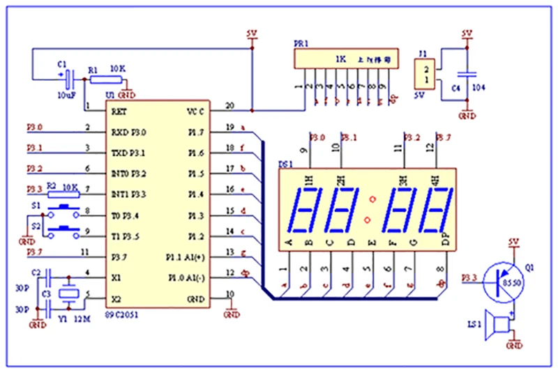 Note: there is direction for PR1 Resisters Packs , there is one side of the word in the direction of the MCU.Pay an attention!!! 6. Component listing | NO. | Component Name | PCB Marker | Parameter | QTY | | 1 | Metal Film Resistor | R1,R2 | 10K | 2 | | 2 | Ceramic Capacitor | C2,C3 | 30pf | 2 | | 3 | Ceramic Capacitor | C4 | 0.1uf 104 | 1 | | 4 | Electrolytic Capacitor | C1 | 10uF/25V | 1 | | 5 | Network Resistor | PR1 | 1K | 1 | | 6 | Crystal Oscillator | Y1 | 12MHz | 1 | | 7 | S8550 | Q1 | TO-92 | 1 | | 8 | Button | S1,S2 | 6*6*5mm | 2 | | 9 | AT89C2051 | U1 | DIP-20 | 1 | | 10 | IC Socket | U1 | DIP-20 | 1 | | 11 | Active Buzzer | LS1 | 5V | 1 | | 12 | Digital Tube | DS1 | 4Bit Red | 1 | | 13 | DC Socket | J1 | 3.5mm | 1 | | 14 | Power Cable | | USB to 3.5mm | 1 | NOTE:Users can complete the installation by PCB silk screen and component listing  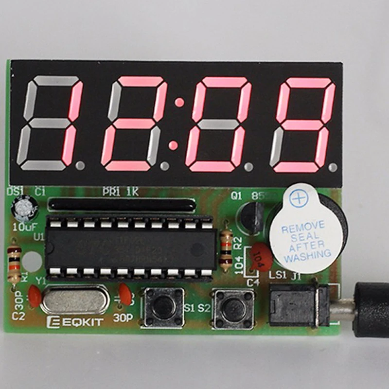 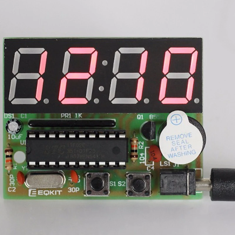 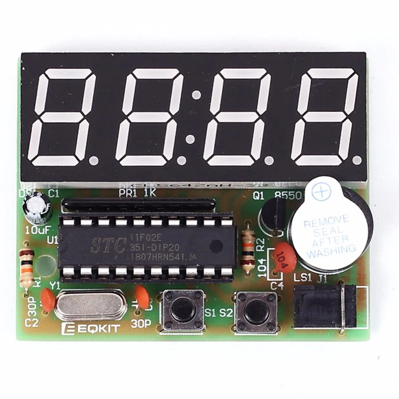 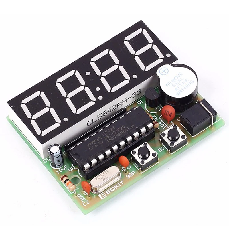 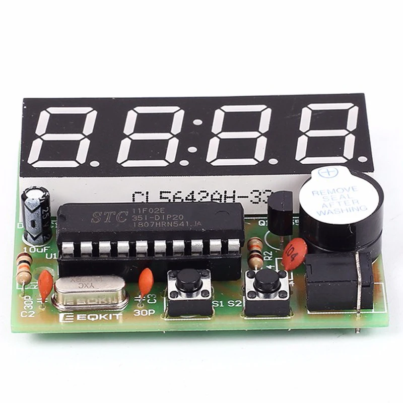 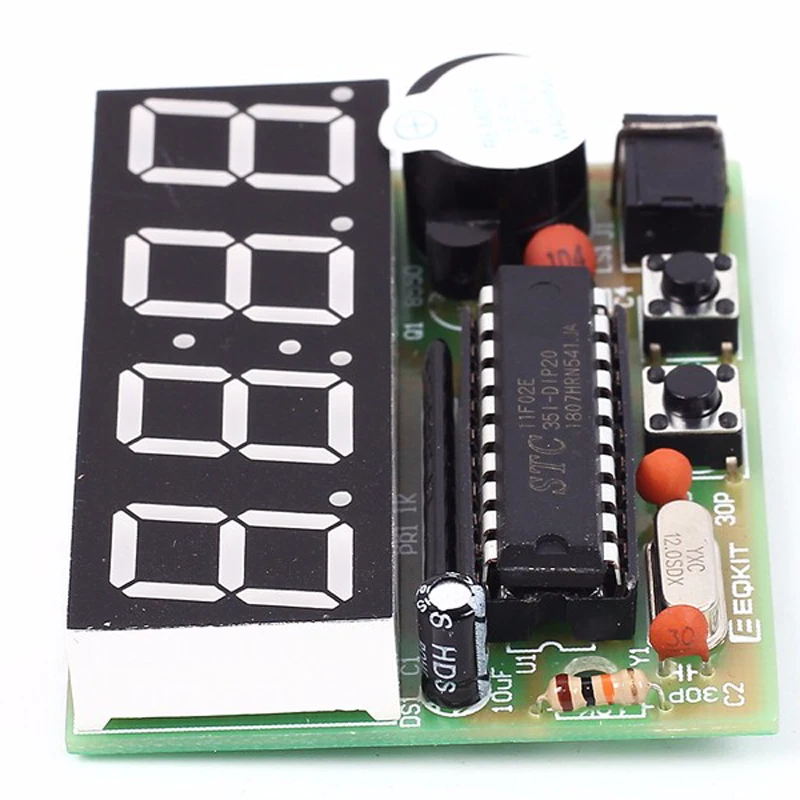       --> -->
|


 배송기간
배송기간