433Mhz Universal Wireless Remote Control Switch DC 12V 4CH relay Receiver Module With 4 channel RF Remote 433 Mhz Transmitter
Application areas:
Remote control garage door \\ Remote control house door \\ Remote control Lamp \\ Remote control curtains \\ Remote control Fun and other remote control device.
Package Included:
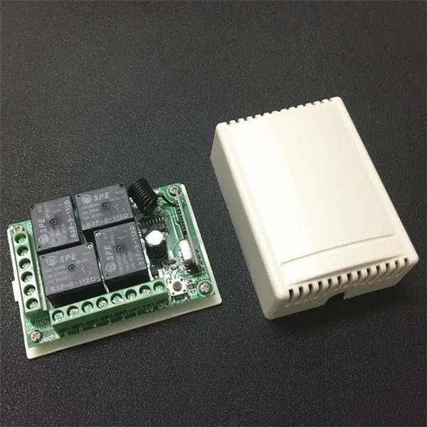
Receiver module (KR1204-4 ) * 1pcs ( include Shell )
Notice: This link does not contain a remote control.
If you need to include the remote control kit, please click the link below to buy:
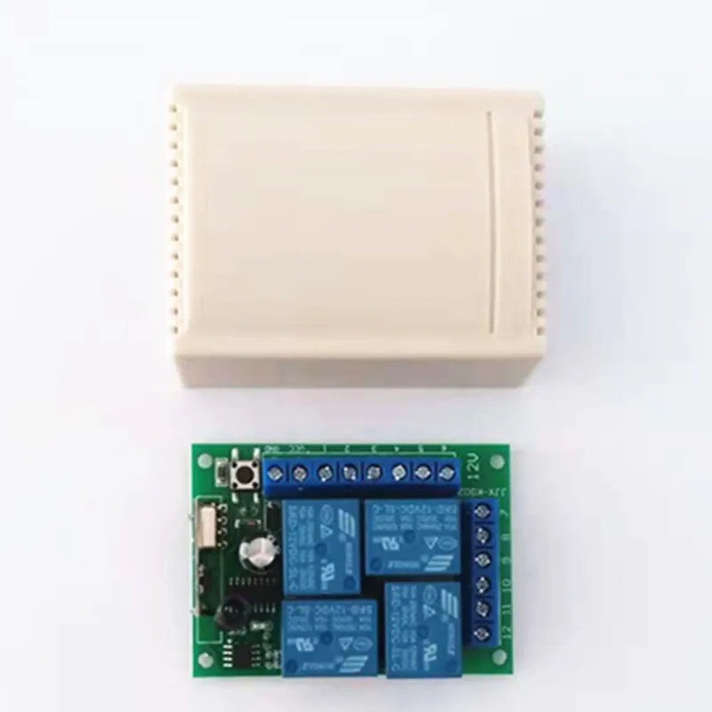
Product Photo

SPECIFICATION
1. Working Voltage: DC12V
2. Quiescent Current: 5mA
3. Working Frequency: 433Mhz
4. Receiving Sensitivity: -104dBm
5. Function option: Momentary/Toggle/Latched
6. Modulation Mode: ASK
7. Matching Mode: Intelligent Learning code
8. Output Mode: Dry contact /Voltage output
9. Shell: Yes
10. Working temperature: -30~+80
11. PCB dimension: 68.2x48.2(mm)
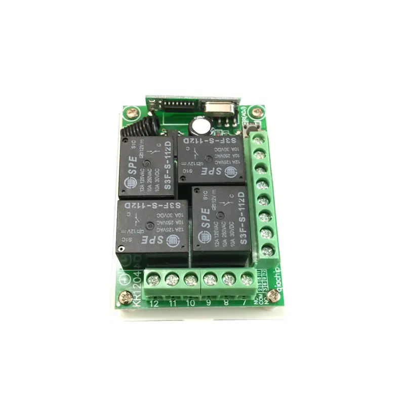
Pin Fucntions
+V mdash Positive pole input
GND mdash Negative pole input
1 mdashKC1 Normal Closed of relay (NC)
2 mdashKC1 Common of relay (COM)
3 mdashKC1 Normal Open of relay (NO)
4 mdashKC3 Normal Closed of relay (NC)
5 mdashKC3 Common of relay (COM)
6 mdashKC3 Normal Open of relay (NO)
7 mdashKC2 Normal Closed of relay (NC)
8 mdashKC2 Common of relay (COM)
9 mdashKC2 Normal Open of relay (NO)
10 mdashKC4 Normal Closed of relay (NC)
11 mdashKC4 Common of relay (COM)
12 mdashKC4 Normal Open of relay (NO)
When the relay is energized, NO and COM connected.
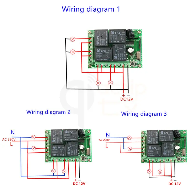
The way of Circuit Connection:?
Please Note: the Receiver Switch Module part number KR1204-4 have 3 ways of working mode.The OUTPUT signal have 2 Voltage Level. It decided by the INPUT of the COM pin.
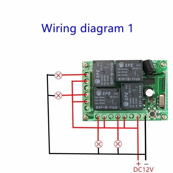
OUTPUT mode 1:
Connect the COM to the Power Supply by DC12V, the Output pin will create DC12V Signal. Please check below diagram for better understanding.
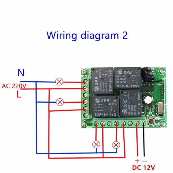
OUTPUT mode 2:
Connect the COM pin with any other Additional Power Supply,the output will create the same Voltage signal as the Additional Power Supply. it can be Direct Current or Alternating Current. Decided by the Additional Power Supply.
BUT, Please note: the additional Power Supply should be in the range of the Receiver Switch Module-(DC5-12V, AC 85-240V).
Please check below diagram for better understanding.
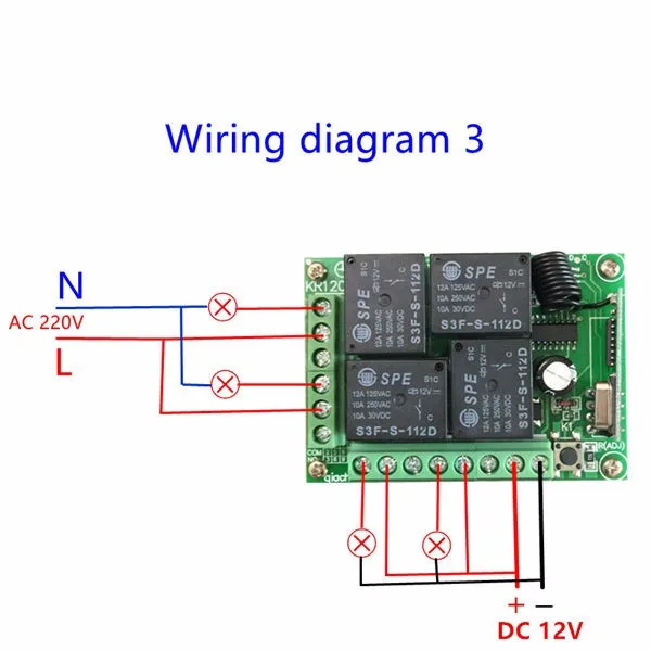
OUTPUT mode 3:
Mix work mode: You can also make 2 channel work under the DC output mode, and 2 with the AC output. Please check below diagram for better understanding.
note
If you don\`t understand. Please use your computer to view the video on the product details page. Learn how to do it, or send us a message.
Instructions:
About Working mode:
1. Momentary/Jog: Press and hold->on; Release->Off
Keep pressing one button , the corresponding channel is working /on;
Loosen your finger is stop/OFF .
(4 channel switch(receiver) need 4 button remote control (transmitter ))
2. Toggle/Self-Lock: Press->on; Press again->Off
Press one button for one time , the corresponding channel is working/on;
Press the same button again is stop/OFF .
(4 channel switch(receiver) need 4 button remote control (transmitter)).
3. Latched/Inter-Lock: Press->on; Press other button->Off
Press one button for one time, the corresponding channel is working/on;
Press another button is stop/OFF(At the same time, another corresponding channel works) .
( 4 channel switch( receiver) need 4 buttons remote control (transmitter).
Note:
When you receive the product, it maybe set in one remote mode randomly, that because each product got test when it can be arranged to shipment.So, if you want to select the remote mode you like, please Delete the existing data for the first step:
How to Delete the existing remote
controls data?
Press the learning key on the Receiver Switch Module board 8 times, then wait for the LED indicator on the board flash for 5 times, the existing data are deleted successfully. ( if the LED indicator on the board doesnrsquot Flash, Please check the Power Supply status, make it right, and try more times)
Please find the Learning Key of the Receiver Switch Module by checking below photo:
1. Relay
2. LED lights
3. Learning button
The setting of working mode:
1. Momentary Mode: pressing one time the learning key button on the receiver board ( Led indicator on receiver board will signaling simultaneously ),then press any of the remote button , signaling three times by remotersquos LED indicator informs about setting momentary mode successfully .
2. Toggle Mode: pressing two times the learning key button on the receiver board( Led indicator on receiver board will signaling simultaneously ),then press any of the remote button , signaling three times by remotersquos LED indicator informs about setting toggle mode successfully .
3. Latched Mode: pressing three times the learning key button on the receiver board ( Led indicator on receiver board will signaling simultaneously ),then press first remote button ,follow on second remote button , signaling three times by remotersquos LED indicator informs about setting latching mode successfully ( first button stands for on , second button stands for off ).
4. 2CH momentary + 2CH Toggle: pressing four times the learning key button on the receiver board(Led indicator on receiver board will signaling simultaneously ),then press any of the remote button , signaling three times by remotersquos LED indicator informs about setting successfully .
5. 2CH Momentary + 2CH Latched: pressing five times the learning key button on the receiver board ( Led indicator on receiver board will signaling simultaneously ),then press any of the remote button , signaling three times by remotersquos LED indicator informs about setting successfully .
6. 2CH Toggle + 2CH Latched: pressing six times the learning key button on the receiver board( Led indicator on receiver board will signaling simultaneously ),then press any of the remote button , signaling three times by remotersquos LED indicator informs about setting successfully .
7. 2CH Latching + 2CH Latched: pressing seven times the learning key button on the receiver board( Led indicator on receiver board will signaling simultaneously ),then press any of the remote button , signaling three times by remotersquos LED indicator informs about setting successfully .
NOTES
1. Please do not charged operation, you should shut off the power, and operation after testing and correct electricity.
2. Please promptly change battery when remote control voltage is insufficient, (when the battery voltage is insufficient, generally get close transmitting )
3. Please pay attention to avoid metal mask,large equipment ,strong interference electromagnetic filed when using wireless RF products,and avoid too short distance between the remote control and receiver board .
4. Please avoid abnormal using of the product.Abnormal using will reduce product performance and life, when seriously it may damage the products and even make danger for your safe .
If you need DC 12V power supply to test, please click below to buy:


 배송기간
배송기간