Packaging Details
- Unit Type: piece
- Package Weight: 0.200kg (0.44lb.)
- Package Size: 30cm x 20cm x 10cm (11.81in x 7.87in x 3.94in)
ow.productDescripti
Free shipping!!!
Manufacturer direct sale ,Impulse promotions, missed !!!
Instructions provided modules and PC debugging computer software documentation, after the buyer photographed please contact the owner to obtain information or to the following URL to download
shwellpro.com/down/html/?9.html
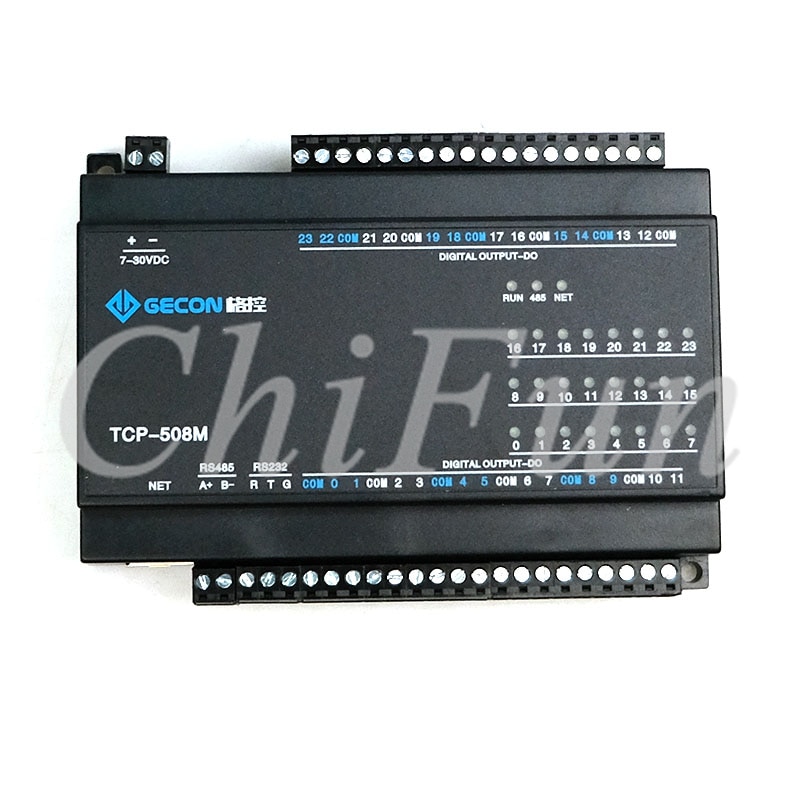
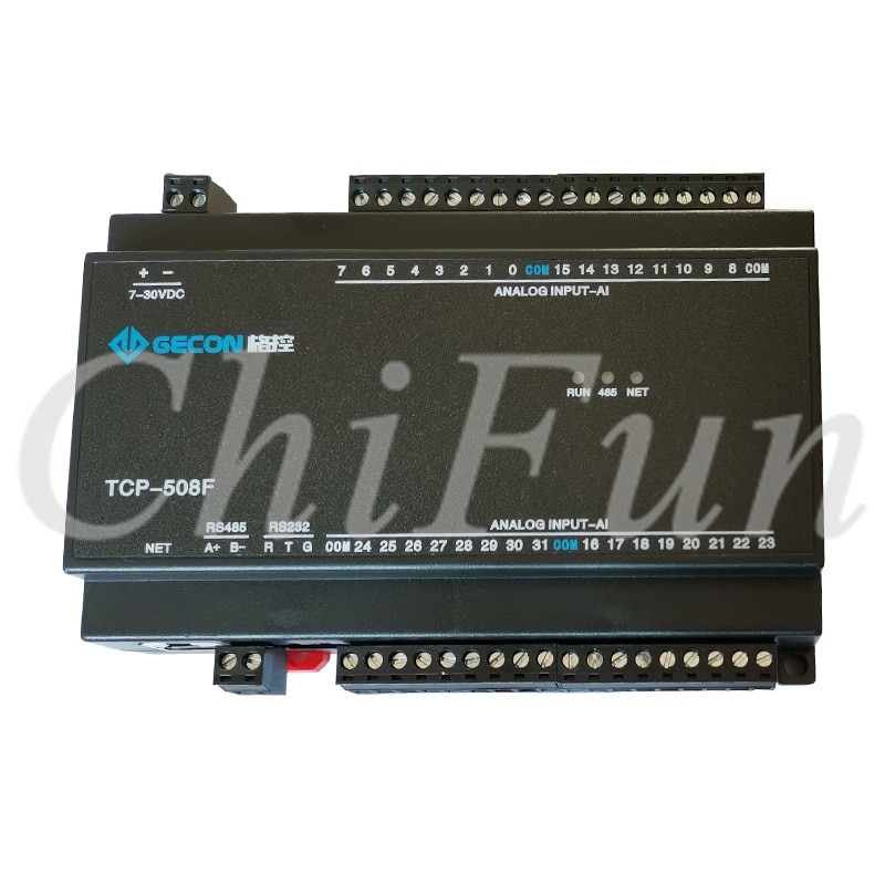
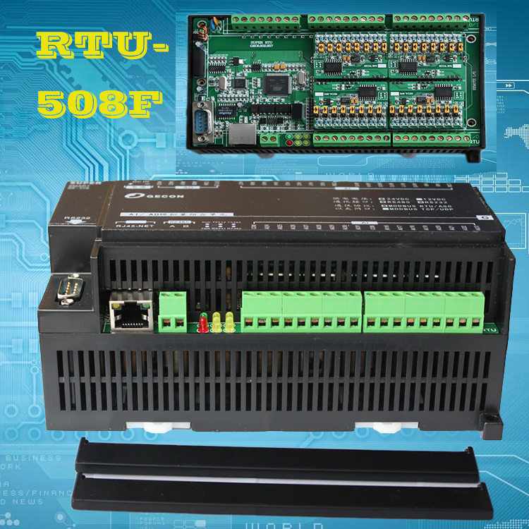
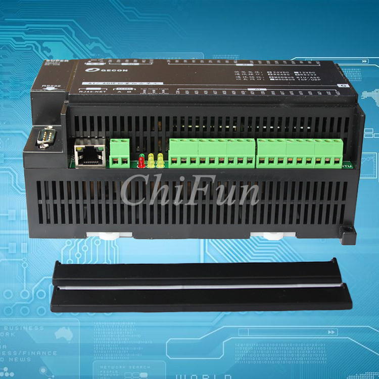
I. Product Overview
l 16Opto-isolated digital output (NPN transistor open collector output )
l Using standard RS485 MODBUS RTU communication , networking and configuration software can be , PLC, industrial touch screen, etc.
l With communication and output status indicator
l Communication circuit lightning , anti-jamming design
l Signal acquisition and control can be widely used in industrial field devices
l Normal three-year warranty
Second, the main parameters
l 16 digital output channels (NPN transistorOpen CollectorOutput ,500mA)
l Operating temperature range -20 ~ 70
l External power supply DC 9V ~ 30V / 2W
l 1500VDC isolation protection
l Standard DIN rail mounting or screw mounting
l Dimensions 125 × 73 × 35mm
Third, the interface definition
| AVcc | External power input positive terminal |
| AGnd | Negative external power input terminal |
| DO_01 | The first digital outputs |
| DO_02 | 2 digital outputs |
| DO_03 | 3 digital outputs |
| DO_04 | 4 digital outputs |
| DO_05 | 5 digital outputs |
| DO_06 | 6 digital outputs |
| DO_07 | Chapter 7 digital outputs |
| DO_08 | Article 8 digital outputs |
| DO_09 | Article 9 digital outputs |
| DO_10 | The first 10 digital outputs |
| DO_11 | 11 digital outputs |
| DO_12 | 12 digital outputs |
| DO_13 | The first 13 digital outputs |
| DO_14 | The first 14 digital outputs |
| DO_15 | 15 digital outputs |
| DO_16 | 16 digital outputs |
| 485A | RS485Signal A + |
| 485B | RS485Signal B- |
Fourth, the digital output application diagram

Fifth, communications instructions
1,Communication Parameter Description ( factory default ): 9600, N, 8,1
| Parameters | Explanation |
| 9600 | Baud Rate |
| N (No parity ) | Parity bit |
| 8 | Data bits |
| 1 | Stop bits |
2The digital output signal control command ( more control ) :
Send : 01 0F 00 00 00 10 02 21 86 7B D2 ( cases / 16 hex )
| Data | Byte | Data Description | Remark |
| 01 | 1 | Module address | Address range 01-FE |
| 0F | 1 | Function code | 0F-Write multiple coils |
| 0000 | 2 | Coil address (0x type ) | 0000-Coil start address |
| 0010 | 2 | Write coil length | 0010-Write 16 coils |
| 02 | 1 | Write data bytes | 02Write two bytes of data |
| 2186 | 2 | Write data | 2186-Write the output state of the coil 16 |
| 7BD2 | 2 | CRCChecksum | In front of all the data of CRC |
Reception : 01 0F 00 00 00 10 54 07 ( cases / 16 hex )
Written data "21" , is converted into a binary number " 00100001 " , from left to right respectively 8 digital output signal status DO_08-DO_01 and write data "86" , converted into 2 system number " 10000110 " , from left to right respectively 8 digital output signal status DO_16-DO_09 , that DO_16, DO_11, DO_10, DO_06, DO_01 with output, no other channel output module receives the correct command after making the appropriate action in accordance with the command and response command sent back to the host , indicating successful communication
3The digital output signal control command ( single control ) :
Send : 01 05 00 00 FF 00 8C 3A ( cases / 16 hex )
| Data | Byte | Data Description | Remark |
| 01 | 1 | Module address | Address range 01-FE |
| 05 | 1 | Function code | 05Single Coil |
| 0000 | 2 | Coil address (0x type ) | 0000-Digital output (DO_01) Coil Address 0001-Digital output (DO_02) Coil Address 0002Digital output (DO_03) Coil Address 0003-Digital output (DO_04) Coil Address 0004-Digital output (DO_05) Coil Address 0005-Digital output (DO_06) Coil Address 0006Digital output (DO_07) Coil Address 0007-Digital output (DO_08) Coil Address 0008-Digital output (DO_09) Coil Address 0009-Digital output (DO_10) Coil Address 000A-Digital output (DO_11) Coil Address 000B-Digital output (DO_12) Coil Address 000C-Digital output (DO_13) Coil Address 000D-Digital output (DO_14) Coil Address 000E-Digital output (DO_15) Coil Address 000F-Digital output (DO_16) Coil Address |
| FF00 | 2 | Write data | FF00-Open coil , the coil close 0000- |
| 8C3A | 2 | CRCChecksum | In front of all the data of CRC |
Reception : 01 05 00 00 FF 00 8C 3A ( cases / 16 hex )
After the module receives the correct command , make the appropriate action in accordance with the command and response command sent back to the host , indicating successful communication
4Digital output state acquisition command :
Send : 01 01 00 00 00 10 3D C6 ( cases / 16 hex )
| Data | Byte | Data Description | |
`;


 배송기간
배송기간