4 Color Available 8x8x8 3D LED Cube Light DIY Kit Squared LED for Electronic Toy Learning Suit Red Blue Green Yellow LED
Description:
3D 8*8*8*8 LED cube is a DIY kit. User should weld and install it. 3D 8 is the all-in-one a work of art, such as a C language, electronic technology. It is reality, economical and highly cost effective. It doesn`t just use for decorate, but also can help you learn more professional knowledge about electronic. And you can achieve more and more gorgeous effect.
Specification:
Power supply voltage: 4.5 - 5.5V
PCB size: approx.11.1*12.7cm
Weight: about 233g
Dynamic 3D effect:
1. Pyramid.
2. Rain graphic effect
3. Leaping graphics effect
4. Rotating graphic effect
5. Square move effect
6. Square light move effect
7. Lamp standard rollover effect
8. Square magnify and shrink effect
9. Reverse lamp
10. TriangIe three-dimensional graphics rotation effect
11. Article lamp running effect
12. PulI screen graphics effect
13. Fast and slow display
Installation steps
1. Separate and Solder the Header Pins
With a wire cutter, break the plastic of the header pins, and separate each header.
Then, solder all the 72 header pins. Make sure all the pins are as vertical as possible.
2. Solder the PCB Bottom Components
Start soldering the smallest components, and then solder the DIP sockets. Don’t connect the chips yet. You should seat the chips when you finish soldering all the PCB components.
Make sure you orient the DIP sockets correctly by following the half-circle orientation.
When the PCB is on the following orientation, the letters of the resistor array should be facing at the back.
3. Solder the PCB Top Components
Start by soldering the smaller components, and then the bigger ones. Pay attention to the components that have polarity. You can use the following figure as a reference on where to place each component.
After soldering all the components, you can place the chips in the sockets.
4. Test the PCB
Place 8 LEDs in the PCB with the anode and cathode place as shown. The cathode should be placed in the headers maker with “C1”, “C2”, “C3”, etc.
Apply 5 V to your circuit, and press the switch. The LEDs should light up and display an animation.
Important note: don’t start soldering any LED grids until you make sure your circuit is working properly.
5. Solder the LEDs` Anodes
Build a Cardboard Grid, bend the LEDs, with the longest lead, the anode (+), to the right, and the shortest lead, the cathode (-) to the left.
Using a needle nose pliers, bend the longest lead backwards with a 90º angle. Insert the LEDs into the cardboard, the LED cathode (the shortest lead) is pointing up. Solder the anodes together.
Warning: Each solder joint shouldn’t take more than 1 or 2 seconds, otherwise you might fry the LED.
7.Connect the Cathodes to the PCB
The next step is inserting the grids in the PCB header pins. You should connect the anodes (+) of the LEDs to the header pins.
Then, connect the cathode of the first row to the “C1” header pin. Connect the cathode of the second row to the “C2” header pin, and so on, until you have all the rows connected to the header pins.
8. Connect the LED Grids Together
Once you’ve soldered all the cathodes, test your LED grid. For that, apply power to your cube and press the switch.
After the first grid is properly placed in the PCB, insert the second LED grid into the PCB. Then, solder the free cathodes leads with the cathodes leads of the previous grid.
Repeat this process until you have all your LED grids in place.
Package Included:
1 * PCB
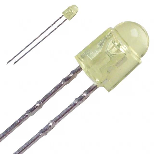
512 * 3mm LED
2 * XH2.54-40P round female pin
9 * 20P IC socket
9 * 74HC573 DIP
1 * USB to DC005 cable
1 * DC005 power socket
1 * 18P IC socket
1 * ULN2803 DIP
1 * 40P IC socket
1 * STC12C5A60S2 (with code)
1 * A09-103 Resisters
1 * 8*8 Self-locking switch
2 * 10uf 25V electrolytic capacitor
1 * 12MHz crystals
2 * 22pf ceramics capacitor
8 * 470ohm resistor
2 * 4.7K ohm resistor
1 * 3mm LED
1 * 0.8mm cable


 배송기간
배송기간